 |
 |
|
Subject: calculate length of lettering on corrugated plate For a client of mine I have to design a lettering on corrugated plate. The lettering has to appear "normal" when viewed from the front (100%) I am so far now to consider the shape of the plate to be two halves of an oval/ellipse. What I would like to know is a way to calculate the percentage in which I have to "stretch" my design in order to let it appear "normal". Probably an unusual question, but one the could be solved in a mathematical way. Kind regards and thanks in advance, Tim
|
|
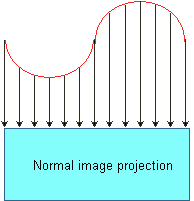
Hi Tim. No single scaling will work properly, because the face is changing all the way along. The task is actually more difficult than just scaling. Look at the following diagram
You can see that I've drawn "projection" lines from the corrugated surface back to the normal image (the arrow can be interpreted in either direction, depending on how you approach things). I've drawn the projection lines at equal spacing with respect to the length of the normal image. If you look carefully at where those projection lines meet the curved print surface, you will at once see that the lengths of the arcs between projection points are not all equal, but depend on what part of the curve you are looking at. To create a compatible "print image", you will need to apply different scaling depending on the lateral position. It is certainly possible to model a mathematical projection based on something like a sine wave, but you are referring to ellipses (which may be an approximation you are using). I'm not a printer, but it seems to me that this is a tough practical problem unless you are equipped to do some serious pixel mapping with a graphics programmer. Can you experiment or is the process to expensive? If you can then you might try a linear scale to see how bad the distortion is. Measure the length of a plate, call the length L1. Corrugate the plate and measure its length. Call this length L2. The units don't matter as long as you use the same units in both cases. Stretch your design by the factor L1/L2, print it on the plate, corrugate it and look at it to determine if the degree of distortion is acceptable. Stephen and Penny. |
 |
 |
 |
